Discover the Process of Making a 4 Wheeler Road Grader Toy
Once a building site has been cleared off by the bulldozer, out comes the road grader to perform the last leveling. After the last leveling is completed, the steamroller is brought in to accomplish the final smoothing process.
Now this guide for constructing a four wheeler road grader possesses all the necessary elements to make this project such a fun, worthwhile pursuit. Those elements are great playability, a toy making process that’s completely beginner-friendly, and a final product that looks realistic enough that children are bound to enjoy playing with the toy for hours on end.
Now this guide for constructing a four wheeler road grader possesses all the necessary elements to make this project such a fun, worthwhile pursuit. Those elements are great playability, a toy making process that’s completely beginner-friendly, and a final product that looks realistic enough that children are bound to enjoy playing with the toy for hours on end.
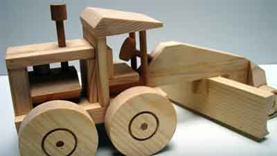
A sort of movable blade is incorporated into the design, and it’s up to you whether you want to place the blade in a straight across position, or have it shifted to either left or right. The toy also features an open-sided engine design component, but you don’t actually have to build the toy engine.
This feature is merely an option so you can opt to construct an engine to go along with the road grader, or simply place a single block of wood in that empty space.
To get this toy from site to site, build a heavy equipment transporter for it just like the one used for the bulldozer. Follow the instructions presented here for the low-boy trailer, but make the trailer floor just a few inches longer.
Read through all the instructions here first to find the sequence for constructing this road grader. And, as with all the four wheeler toy making instructions posted on this website—enjoy!
PROCEDURE FOR MAKING THE ROAD GRADER TOY
1. BASE
Begin by taking the base and gluing the rear axle holders in place. Clamp the stock securely and allow the assembly to set overnight to make sure the glue is thoroughly dry. After the glue has dried, drill the 7/16"-diameter axle holes, then set the base assembly aside.
2. WHEELS
To make the rear wheels, laminate three pieces of 3/4" stock together to form a 2-1/4" x 3-1/2" x 8" piece of stock. Clamp the stock securely and allow the glue to dry thoroughly as for the base assembly. Once the glue has dried, use a handsaw or scroll saw to cut out two 3" diameter wheels.
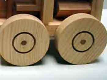
Next, resaw these 2-1/4"-thick blanks to form the 1 -1/8"-thick wheels. Next, take the wheels and, using a 1 -1/4"- diameter hole saw, cut a 1/4'’-deep saw kerf in each one to form the boundary between the tire and the rim. Drill out the 1/4" holes created by the hole saw to a 3/8" diameter with a 3/8" twist drill bit.
Form the smaller front wheels with a 2-1/8" hole saw. The rims for these wheels are created with a 1-1/4" hole saw.
NOTE: To save time later, use a 2-1/8"-diameter hole saw to cut out the blade pivot ring; a 1"- diameter hole saw to cut out the blade pivot pinlock; and a 1-3/8" hole saw to cut out the steering wheel. Sand all these parts and set aside.
3. ENGINE
Building the engine takes a little time, but it really adds a lot of interest to the model. The engine consists of a simple block of wood measuring 1-3/8" x 2-1/4" x 2", but start with a block at least 12" long for safe handling while machining.
Begin by constructing the block. Set up a table saw to cut the necessary bevels on a 12"-long piece of glued-up stock. After cutting the bevels, drill l/2"-diameter holes for the pistons according to the instruction. Next, drill a 3/4"- diameter hole in the top of the engine for the air cleaner. Glue the pistons and air cleaner into place, then set the engine aside.
4. ENGINE COMPARTMENT
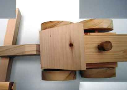
Glue and clamp the engine hood to the engine radiator and the engine hood support. If you made the simple engine block in the last section, glue it. into place at this time. Note that the engine hood should overhang the wood block about 1/8" on each side. Finally, round the top and side edges of the hood. Set the assembly aside.
5. CAB
Begin construction of the cab by cutting the contours on the roof. First, tilt the handsaw table 45° and cut the rear bevel. Then, reset the table to 10“and cut the front bevel. If you do not have a bandsaw, use a belt Sander or hand plane.
After beveling the top of the roof, mark the front edge 1/2" in from the sides and draw a line from the front edge back to the peak (see image below). Cut along these lines to complete the top contour of the roof.
Form the smaller front wheels with a 2-1/8" hole saw. The rims for these wheels are created with a 1-1/4" hole saw.
NOTE: To save time later, use a 2-1/8"-diameter hole saw to cut out the blade pivot ring; a 1"- diameter hole saw to cut out the blade pivot pinlock; and a 1-3/8" hole saw to cut out the steering wheel. Sand all these parts and set aside.
3. ENGINE
Building the engine takes a little time, but it really adds a lot of interest to the model. The engine consists of a simple block of wood measuring 1-3/8" x 2-1/4" x 2", but start with a block at least 12" long for safe handling while machining.
Begin by constructing the block. Set up a table saw to cut the necessary bevels on a 12"-long piece of glued-up stock. After cutting the bevels, drill l/2"-diameter holes for the pistons according to the instruction. Next, drill a 3/4"- diameter hole in the top of the engine for the air cleaner. Glue the pistons and air cleaner into place, then set the engine aside.
4. ENGINE COMPARTMENT
Glue and clamp the engine hood to the engine radiator and the engine hood support. If you made the simple engine block in the last section, glue it. into place at this time. Note that the engine hood should overhang the wood block about 1/8" on each side. Finally, round the top and side edges of the hood. Set the assembly aside.
5. CAB
Begin construction of the cab by cutting the contours on the roof. First, tilt the handsaw table 45° and cut the rear bevel. Then, reset the table to 10“and cut the front bevel. If you do not have a bandsaw, use a belt Sander or hand plane.
After beveling the top of the roof, mark the front edge 1/2" in from the sides and draw a line from the front edge back to the peak (see image below). Cut along these lines to complete the top contour of the roof.
Now place the roof flat, on the base with the front edge of the roof flush with the front of the base, then set the engine compartment on the base against the rear of the roof. The engine compartment radiator should overhang the base by approximately 3/8". If it doesn’t, cut or sand the front edge of the roof so that the engine compartment overhangs the proper amount.
Once the roof is the proper size, mark the position of the 3/8"-diameter cab front supports. Set the front edge even with the front of the base and drill the holes in both parts at the same time.
To secure the stock, use masking tape or double-sided carpet tape between the two parts. Drill two 1/8"-diameter holes located 3/16'' from the back edge of the roof. These holes will act as pilot holes for doweling later.
Begin assembly by first gluing the engine and engine hood assembly to the base.
Clamp these assemblies securely. Once the glue has cured, glue the cab rear panel to the engine compartment and base. Now insert the two cab forward supports into place and attach the cab roof.
Using the pilot holes in the rear of the cab roof, drill holes for 3/16" dowels through the roof and cab rear panel. Glue the dowels in place. Since the dowels at the front and rear of the cab roof will protrude, sand them flush once the glue has dried.
6. FRAME
Transfer the design for the frame to the stock and cut out with a handsaw or scroll saw. Next, take the front axle supports and cut the front profile of these pieces. Glue and clamp the axle supports to the frame.
After the glue has dried, drill the 5/'16"-diameter axle hole as indicated. At the same time, drill a 1/4"-diameter hole somewhere above the axle hole for a reinforcing dowel pin; then, drill the 1/4-"-diameter steering column hole.
Finally, tilt the bandsaw table 45 degrees and cut the front bevel on the axle supports.
7. BLADE
The blade is made by one of two methods. The first method is to cove the stock using the table saw, a procedure described in many woodworking books and websites.
If you elect to cove the blade using the table saw, be careful to follow all of the manufacturer's safety instructions. When coving stock for the road grader, start with a piece at least 18" long. Cut the stock to length after you've completed the cove.
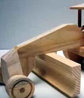
Another method, one that’s much safer, is to use the spindle end of either a handheld or stationary belt sander. Use coarse sandpaper for this operation and, as in the previous method, begin with stock that’s longer than required and cut it to length when the coving has been completed.
Next, take the blade back support and cut bevels on each side of it. Glue the back support to the blade.
NOTE: The bottom of the blade and the back support are still square to provide a firm support for drilling.
After the glue has dried, glue and clamp the blade pivot ring to the blade assembly. Once the glue has dried, drill the 1/2"-diameter hole for the blade pivot pin as shown in the image above.
Complete the blade assembly by cutting or power sanding the bevel on the back of the blade and blade support.
8. SWIVEL ASSEMBLY
The blade on this road grader swivels from side to side. To make the blade swivel, Lake the blade retaining block and, using a 1” drill bit, drill a hole in the center of the block to a depth of 1/2".
Next, drill a 1/2"-diameter hole through the remainder of the stock. Once you've drilled the two holes, take the blade pivot pinlock you made in step 2 and drill out the 1/4" pilot hole to 1/2". Glue the blade pivot pin into the pivot pinlock.
Insert the pivot pin assembly through the blade retaining block (R), then glue and clamp part R to the frame. Be careful not to get any glue in the pivot recess. Once the glue has dried, glue the blade pivot pin into the blade assembly.
9. ASSEMBLY
Begin assembly by gluing the steering column into the frame; then glue the steering wheel to the column. Now glue and clamp the frame to the base. After the glue has dried, drill through the base and frame as indicated for dowel reinforcement. Glue the seat in place and glue the wheels to the axles.
To make the exhaust stack, drill a 1/4"-diameter hole in the engine hood and into the engine block; then glue the stack into place.
10. FINISHING TOUCHES
If you want to paint this toy, use equipment yellow on the body and inside the wheels. Use black on the wheels, engine, seat, blade, steering wheel, and exhaust stack.
